Lesson 3
INTERPRET TECHNICAL DRAWINGS AND PLANS
LO 1. analyze signs, symbols and data; and
LO 2. interpret technical drawings and plans.
LO 2. interpret technical drawings and plans.
Definition of Terms
- Ampere (I) - the unit of electrical current (coulombs per second)
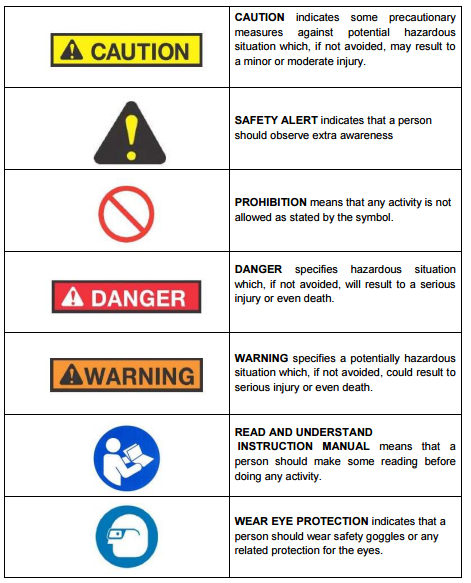
- Caution - indicates some precautionary measures against potential hazardous situation which, if not avoided, may result to a minor or moderate injury
- Danger - specifies hazardous situation which, if not avoided, will result to a serious injury or even death
- Isometric - a kind of drawing which shows the object in 3 dimensional views
- Joule (J) - a metric unit of energy: watt per second. 1 Kw hr = 2,655,000 ft-lb = 1.341 hp-hr = 3413 Btu = 3,600,000 joules
- Kilovolt-ampere (KVA) - a measurement of apparent electric power
- Kilowatt hour (Kwhr) - a unit of electrical energy or work performed Ohm - the unit of electrical resistance (volts/ampere) Orthographic - a drawing which shows the front top and side view of the object
- Volt (E) - the unit of electric pressure or electromotive force which will produce a current of 1 ampere through a resistance of 1 ohm Watts (W) and kilowatts (KW) - are units of electric power
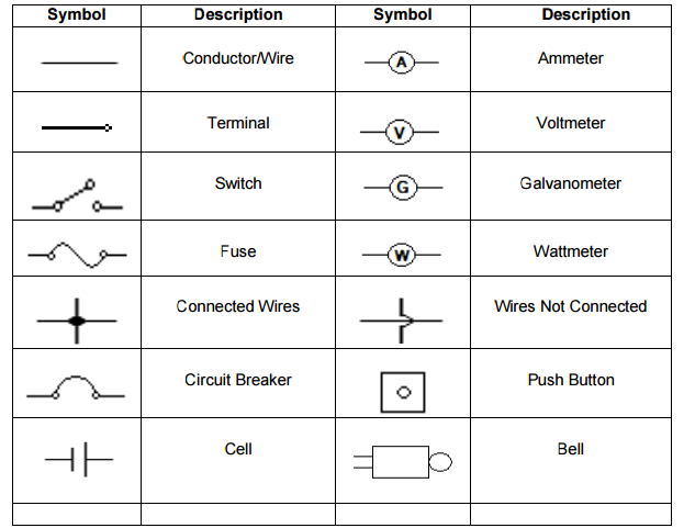
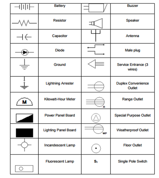
COMMON ELECTRICAL SYMBOLS
Electrical Symbols are small drawings or pictograms used to represent various electrical devices in a diagram or plan of an electrical circuit. These symbols are used in sketching schematic diagrams and electrical plans for numerous types of electrical works. Practically any electrical fixture found in a house has a symbol that coincides to said fixture on an electrical wiring diagram. These are very useful guide for an electrician or electrical contractor, thus, making the wiring easier to install as well.
ELECTRICAL SIGNS
- Your power tool with its manual may contain "WARNING ICONS" (a picture symbol intended to alert you to, and/or to instruct you how to avoid a potentially hazardous condition). Knowing and understanding these symbols will help you operate your tool better and more safely.
Electrical signs and stickers alert students, workers, and visitors to electrical hazards in the area. Alerting workers to high voltage areas, electrical hazards, power lines and other electrical equipment in the area, can help prevent fires and injuries. Proper electrical signs can inform workers of the dangers in the area.
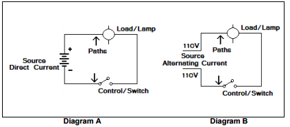
ELECTRICAL WIRING DIAGRAM
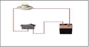
- The flow of current in a conductor or wire can be represented by diagram. There are two types of diagram: pictorial diagram and schematic diagram.
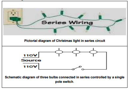
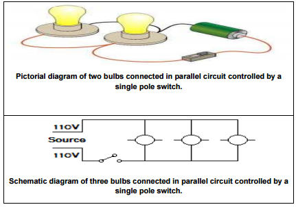
A. Pictorial diagram is a sketch of electrical circuit that shows the external appearance of each component. It is much like a photograph of the circuit and uses simple images of parts.
B. Schematic diagram is a sketch showing the components of the circuit using standard electrical symbols. It shows the actual number of components and how the wiring is routed but not the actual location.
C. Types of Circuit 1. Series Circuit is a circuit in which lamps are arranged in a chain, so that the current has only one path to take. The current is the same through each load. Example of this is the Christmas lights. It consists of a number of bulbs that are connected side by side to meet the voltage requirement which is 220 volts for alternating current.
2. Parallel Circuit is a circuit in which lamps are connected across the wires. The voltage across each load
on parallel circuit is the same. The advantage of using parallel circuit is that even if one of the lamps fails, still the remaining lamps will function.
on parallel circuit is the same. The advantage of using parallel circuit is that even if one of the lamps fails, still the remaining lamps will function.
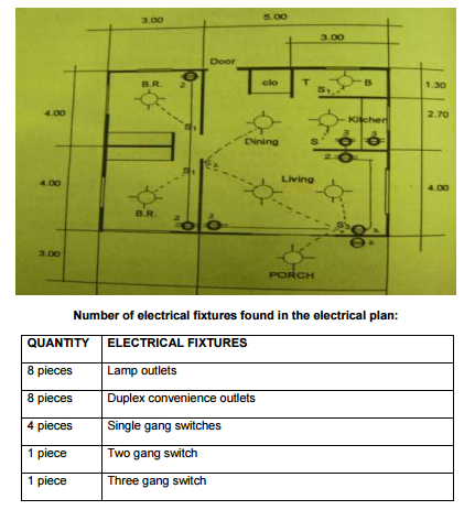
ELECTRICAL PLAN
- Electrical plan is a graphical presentation of electrical wiring connections to install in a particular house or building. It indicates the position of electrical fixtures such as convenience outlets, switches, lightings, door bells, and others to be installed
Sample electrical plan of Single family dwelling