Lesson 4:
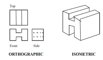
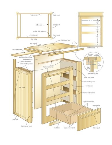
INTERPRET DRAWINGS AND PLANS
LEARNING OUTCOMES:
At the end of this Lesson, you are expected to do the following:
At the end of this Lesson, you are expected to do the following:
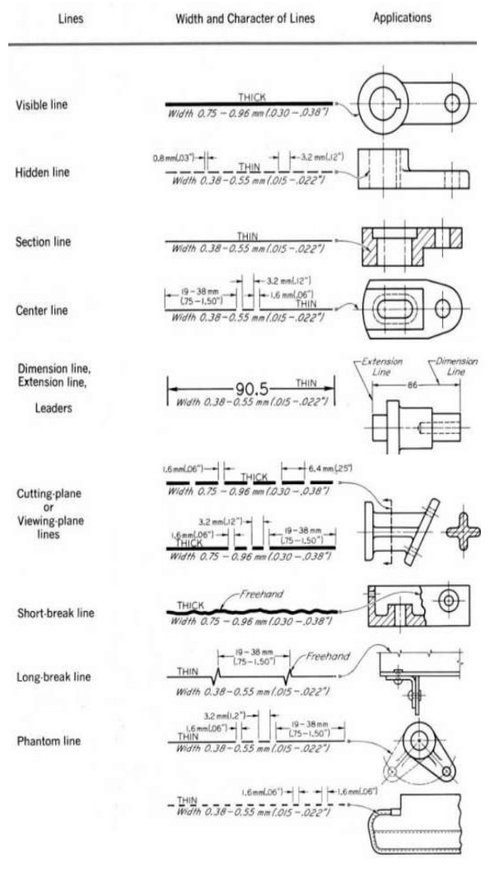
- LO 1. analyze signs, symbols and data;
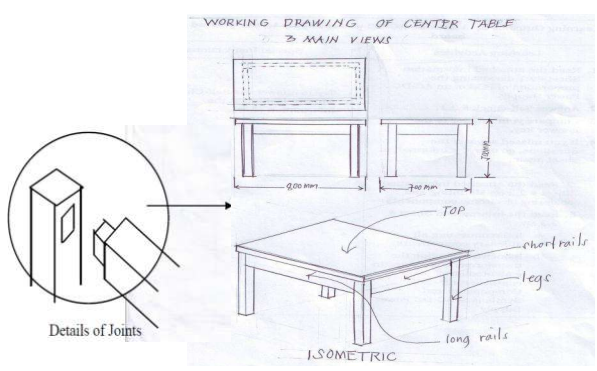
- LO 2. interpret technical drawings and plans; and
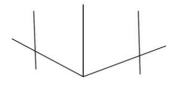
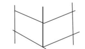
- LO 3. apply freehand sketching.